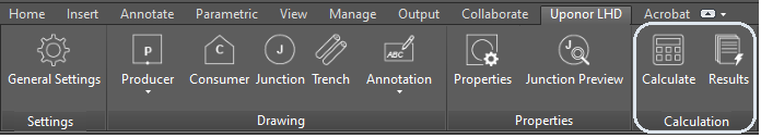
Get started
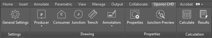
The main ribbon consist of five categories of buttons - the introduction of settings and processing of the drawing, insertion of components and annotations, calculations and preview of results, printouts.
Settings
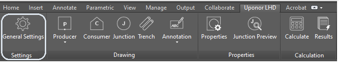
General Settings
The button opens the General settings window.
Drawing
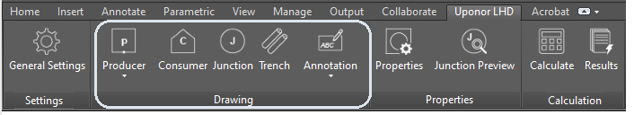
Producer
The producer must be inserted to proceed with the design process. When inserting the producer, select a specific number of outputs from the drop-down list.
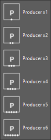
Below an example of the Producer with one ouput.
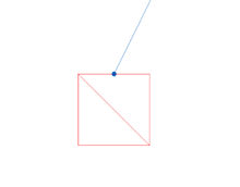
NOTE 1! Proper insertion of the icon is very important.
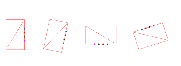
It can not be rotated. Below are examples of incorrect producer placement.
In such cases, the project will not be calculated and an error message will be displayed:
[Error] „The producer has been rotated, please restore it to original
position”.
NOTE 2! It is also important that the selected type of Producer has the appropriate number of
outputs.
This means that when inserting an icon of a producer with one output,only one trench will
be drawn.
If another line is inserted, the program will display an error message:
[Error] “The Producer has more Trenches connected than number of the circuits. Only one Trench can be connected to one circuit.
Select Producer with more circuts.
Consumer
Before inserting a component into the drawing, a window with data will appear, more extensively explained in the Consumer description.
The Consumer icon can be inserted in custom preferences – it can be rotated.
Junction
The junction element is used to connect consumers to the producer. Below is an example of a junction box with 6 outputs.
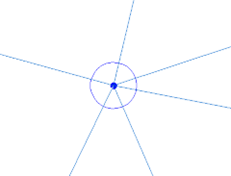
NOTE! From one junction, a maximum of 7 outputs can be connected.
If more trenches are inserted, an error message will appear:
[Warning] „The created connection in the  [Name Junction] is impossible.
The maximum number of Trenches in Junction is 8.
Trench
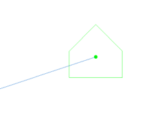
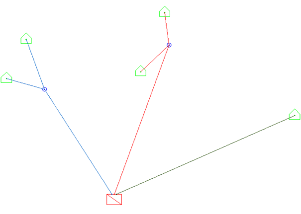
A trench refers to a line connecting components. During the drawing process, it appears in green color. It is important to ensure that the line remains green during drawing; otherwise, it should be deleted and inserted again. In the finalized project, the lines are marked in blue.
In the project below, a part of the path required redesigning. The blue trenches were already calculated and marked, while the newly inserted path is highlighted in green.
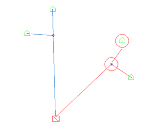
After performing calculations, unconnected elements are marked with a red circle.
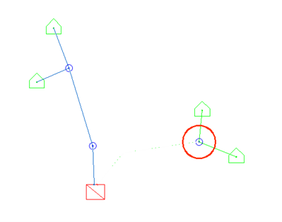
It is necessary to check the correctness of the connection and recalculate the project if needed.
In case the producer has more than one departure, for each circuit its layer must be changed via layer properties in the AutoCAD ribbon.
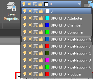
Below an example:
NOTE! The layers should be changed before the hydraulic calculations.
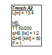
Annotations
The previously defined data for annotations are placed on the drawing after clicking the Annotations button. There is an option to manually insert annotations for each drawn element or automatic annotation generation for the entire drawing.
When choosing the option for manually inserting annotations, you need select the item and specify the location where the table should be placed on the drawing.
Automatic annotations
Automatically inserting annotations will place a label next to each component on the drawing. The placement of the table can be edited, allowing you to adjust its location on the drawing.
Properties
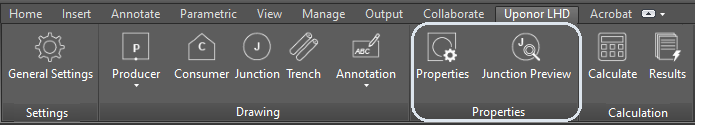
Properties
The Info button allows to preview and modify the settings entered for inserted elements such as producers, consumers, junctions and trenches. The window for this functionality is further defined in the description of the respective inserted elements.
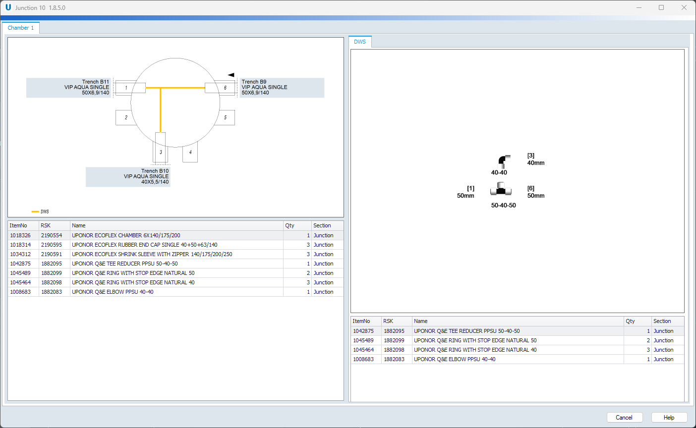
Junction Preview
The option to preview the selected junction.
Calculation
Calculations
After clicking on the hydraulic calculations button, if there are no errors in the project, the plug-in will run calculations and generate the project report. If there are any errors or warnings, the list of issues will be displayed.The errors can be preview later on command text box.
Results
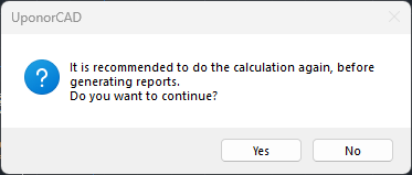
By clicking on this button, the user can access a summary or detailed overview of the previously calculated results. The results window is described in detail in the "Results" chapter. Before generating the report, the program always prompts for project recalculation.